Important NoteThis entire repo was AI created - including all of the data within. The intent was to A) help me with my personal electronics inventory; and B) see how I could use AI to make that process a bit easier. DO NOT TRUST!
Adafruit Feather M0 Express
Details
- Location: Cabinet-1, Bin 29
- Category: Feather Boards
- Type: ATSAMD21 Development Board (Feather Form Factor)
- Microcontroller: ATSAMD21G18 ARM Cortex-M0+ @ 48MHz
- Brand: Adafruit
- Part Number: 3403
- Quantity: 3
- Product URL: https://www.adafruit.com/product/3403
Description
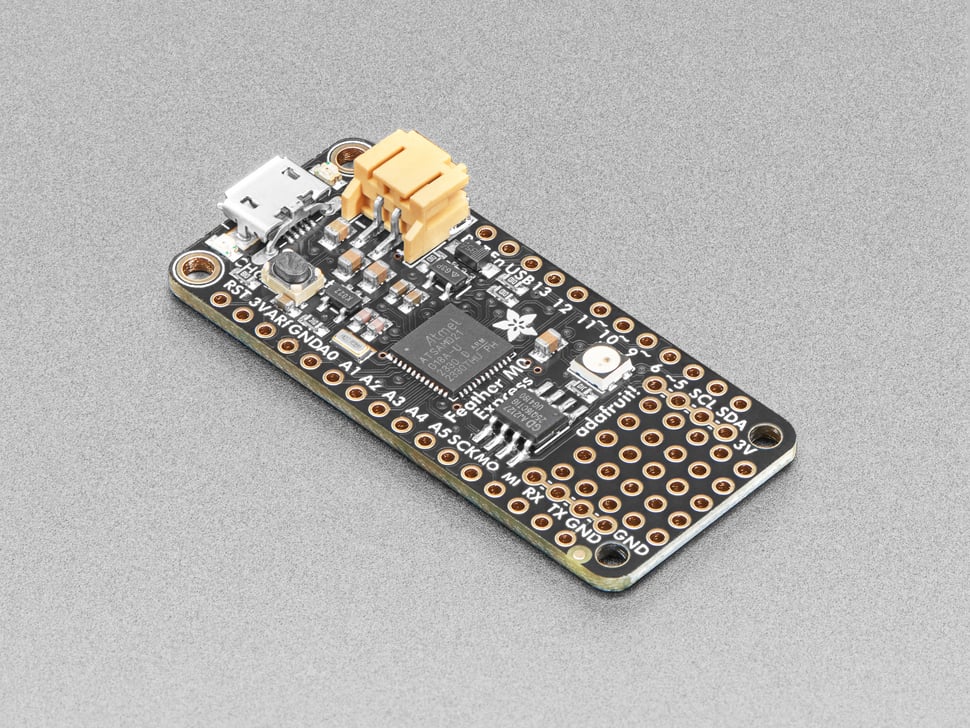
The Adafruit Feather M0 Express features an ATSAMD21G18 ARM Cortex M0+ processor with built-in USB, making it perfect for CircuitPython and Arduino projects. It includes 2MB SPI Flash storage, a Mini NeoPixel, and prototyping space, making it an excellent choice for learning and development.
Specifications
- Microcontroller: ATSAMD21G18 @ 48MHz with 3.3V logic/power
- Memory: 256KB Flash, 32KB SRAM (no EEPROM)
- External Storage: 2MB SPI Flash for CircuitPython files and data logging
- GPIO Pins: 20 total
- ADC: 6x 12-bit analog inputs
- DAC: 1x 10-bit analog output
- PWM: PWM outputs on all pins
- Peripherals: Hardware Serial, I2C, SPI support
- USB: Native USB support with UF2 bootloader
- Power: 3.3V regulator with 500mA peak current output
- Clock: 32.768 KHz crystal for clock generation & RTC
Dimensions
- Board Size: 51mm x 23mm x 8mm (2.0” x 0.9” x 0.28”)
- Weight: 5g (light as a large feather!)
- Form Factor: Standard Feather compatible
Image
Features
- Standard Feather form factor compatible with all FeatherWings
- Pre-loaded with UF2 bootloader for easy programming
- Drag-and-drop programming - appears as USB storage device
- CircuitPython support with 2MB Flash for file storage
- Arduino IDE compatible (bossa-compatible)
- Built-in 100mA LiPoly charger with charging status LED
- Pin #13 red LED for general purpose blinking
- Mini NeoPixel for colorful status indication
- Real Time Clock (RTC) with 32.768 KHz crystal
- 4 mounting holes and reset button
- Power/enable pin for low-power applications
- Small prototyping area for custom circuits
Programming Options
- CircuitPython: Drag-and-drop Python programming with 2MB storage
- Arduino IDE: Full Arduino support with SAMD21 core
- UF2 Bootloader: Mass storage programming interface
- PXT MakeCode: Block-based programming support
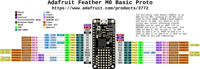
Pinout Diagram
Basic Wiring Examples
LED Blink Circuit
Feather Pin 13 → Built-in Red LED (no external wiring needed)
OR
Feather Pin 5 → LED Anode (long leg)
LED Cathode (short leg) → 220Ω Resistor → Feather GND

Note: Pin 13 has built-in red LED
Button Input Circuit
Feather 3V → 10kΩ Pull-up Resistor → Feather Pin 5
Feather Pin 5 → Button → Feather GND

Code: digitalRead(5) returns HIGH when not pressed, LOW when pressed
I2C Device Connection (STEMMA QT Compatible)
I2C Device VCC → Feather 3V
I2C Device GND → Feather GND
I2C Device SDA → Feather Pin 20 (SDA)
I2C Device SCL → Feather Pin 21 (SCL)

Note: Built-in pull-up resistors included
SPI Device Connection
SPI Device VCC → Feather 3V
SPI Device GND → Feather GND
SPI Device SCK → Feather Pin SCK
SPI Device MOSI → Feather Pin MOSI
SPI Device MISO → Feather Pin MISO
SPI Device CS → Feather Pin 10 (or any digital pin)
Analog Sensor Reading
Sensor Output → Feather Pin A0-A5 (6 analog inputs available)
Sensor VCC → Feather 3V
Sensor GND → Feather GND

Code: analogRead(A0) returns 0-1023 (10-bit ADC)
DAC Output (True Analog)
Audio/Analog Output → Feather Pin A0 (DAC)
Connect to amplifier input or analog circuit
Output range: 0-3.3V analog

Note: True 10-bit DAC, not PWM
Serial Communication
Device TX → Feather Pin 0 (RX)
Device RX → Feather Pin 1 (TX)
Device VCC → Feather 3V
Device GND → Feather GND

Code: Serial1.begin(9600) for hardware UART
Battery Connection
LiPo Battery JST Connector → Feather BAT pin
Battery voltage monitoring → Feather Pin 9 (A7)

Note: Built-in charging circuit, automatic USB/battery switching
Programming Setup Guide
CircuitPython Setup (Recommended)
- Download CircuitPython UF2 from circuitpython.org
- Double-click reset button to enter bootloader mode
- Drag UF2 file to FEATHERBOOT drive
- Board reboots as CIRCUITPY drive
- Edit code.py to program
Arduino IDE Setup
- Install Arduino IDE
- Add Adafruit SAMD boards package URL in preferences
- Install “Adafruit SAMD Boards” package
- Select “Adafruit Feather M0 Express” from Tools → Board
- Double-click reset for first upload
UF2 Bootloader
- Double-click reset button
- Board appears as FEATHERBOOT drive
- Drag UF2 files to program
- Automatic reboot after programming
Programming Examples
CircuitPython Basic LED Blink
import board
import digitalio
import time

led = digitalio.DigitalInOut(board.D13)
led.direction = digitalio.Direction.OUTPUT

while True:
    led.value = True
    time.sleep(0.5)
    led.value = False
    time.sleep(0.5)
CircuitPython NeoPixel Control
import board
import neopixel
import time

# Built-in NeoPixel
pixel = neopixel.NeoPixel(board.NEOPIXEL, 1, brightness=0.3)

colors = [(255, 0, 0), (0, 255, 0), (0, 0, 255), (255, 255, 0)]

while True:
    for color in colors:
        pixel[0] = color
        time.sleep(0.5)
CircuitPython I2C Scanner
import board
import busio

i2c = busio.I2C(board.SCL, board.SDA)

while not i2c.try_lock():
    pass

print("I2C addresses found:", [hex(device_address)
      for device_address in i2c.scan()])

i2c.unlock()
Arduino Basic LED Blink
void setup() {
  pinMode(13, OUTPUT);  // Built-in LED
}

void loop() {
  digitalWrite(13, HIGH);
  delay(1000);
  digitalWrite(13, LOW);
  delay(1000);
}
Arduino DAC Output
void setup() {
  analogWriteResolution(10);  // 10-bit DAC resolution
}

void loop() {
  // Generate sine wave on DAC output (pin A0)
  for (int i = 0; i < 360; i++) {
    float radians = i * (PI / 180.0);
    int dacValue = (sin(radians) + 1.0) * 511.5;  // 0-1023 range
    analogWrite(A0, dacValue);
    delayMicroseconds(100);  // ~10kHz sample rate
  }
}
Arduino Battery Monitoring
void setup() {
  Serial.begin(9600);
  while (!Serial);
  Serial.println("Feather M0 Express Battery Monitor");
}

void loop() {
  // Read battery voltage (connected through voltage divider)
  int batteryReading = analogRead(A7);
  float batteryVoltage = batteryReading * (3.3 / 1023.0) * 2.0;  // Voltage divider

  Serial.print("Battery voltage: ");
  Serial.print(batteryVoltage);
  Serial.println("V");

  if (batteryVoltage > 4.0) {
    Serial.println("Battery: Full");
  } else if (batteryVoltage > 3.7) {
    Serial.println("Battery: Good");
  } else if (batteryVoltage > 3.4) {
    Serial.println("Battery: Low");
  } else {
    Serial.println("Battery: Critical");
  }

  delay(5000);
}
Important Notes
Power Considerations
- 3.3V Logic: All GPIO pins are 3.3V logic level
- USB Power: Powered via USB with automatic switching
- Battery Power: Built-in LiPo charging and management
- Current Limit: 500mA peak from 3.3V regulator
- Power Monitoring: Battery voltage available on pin A7
Pin Capabilities
- Digital I/O: 20 pins total
- Analog Input: 6 pins (A0-A5) with 12-bit ADC
- Analog Output: 1 true DAC pin (A0) with 10-bit resolution
- PWM: All digital pins support PWM
- Touch Sensing: Not available on ATSAMD21
Special Features
- CircuitPython Optimized: Designed specifically for CircuitPython
- UF2 Bootloader: Drag-and-drop programming
- SPI Flash: 2MB for CircuitPython files and data
- Built-in NeoPixel: RGB status indicator
- Feather Ecosystem: Compatible with all FeatherWings
Programming Considerations
- Double-click Reset: Enter bootloader mode for programming
- CircuitPython Priority: Optimized for CircuitPython development
- Arduino Compatible: Full Arduino IDE support
- Memory Management: 32KB SRAM, 256KB Flash + 2MB SPI Flash
Tags
microcontroller, atsamd21, feather, circuitpython, arduino, m0-express, battery-charging, adafruit, neopixel, spi-flash, uf2
Notes
This was Adafruit’s first board designed specifically for CircuitPython, though newer boards like the M4 series offer better performance. The 2MB SPI Flash acts as storage for CircuitPython scripts and libraries, or can be used as a tiny hard drive in Arduino projects. The UF2 bootloader makes programming incredibly easy - just drag firmware files to the board. Perfect for beginners learning CircuitPython or Arduino programming.