Important NoteThis entire repo was AI created - including all of the data within. The intent was to A) help me with my personal electronics inventory; and B) see how I could use AI to make that process a bit easier. DO NOT TRUST!
Adafruit LSM6DS33 6-DoF IMU
6-axis inertial measurement unit combining 3-axis accelerometer and 3-axis gyroscope with STEMMA QT connectivity for easy plug-and-play integration.
Overview
The Adafruit LSM6DS33 6-DoF IMU is a breakout board featuring ST’s LSM6DS33 sensor that combines a 3-axis accelerometer and 3-axis gyroscope in a single package. The board includes voltage regulation, level shifting, and STEMMA QT connectors for easy integration with microcontroller projects.
Note: This product has been discontinued and replaced by the LSM6DS3TR-C.
Key Features
6-Axis Motion Sensing
- 3-axis accelerometer for linear acceleration measurement
- 3-axis gyroscope for angular velocity measurement
- Configurable ranges for both sensors
- High resolution 16-bit output
- Advanced features including tap detection and free-fall detection
Easy Integration
- STEMMA QT connectors for plug-and-play I²C connection
- Voltage regulation for 3V or 5V operation
- Level shifting for mixed voltage systems
- Multiple interfaces (I²C and SPI)
- Compact design with mounting holes
Technical Specifications
Electrical Characteristics
- Operating Voltage: 3.0V to 5.5V
- Supply Current: 0.9mA (accelerometer + gyroscope active)
- Interface: I²C (up to 400kHz) or SPI (up to 10MHz)
- Logic Levels: 3.3V with 5V tolerance
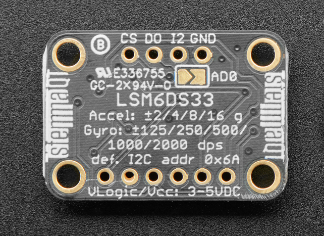
- I²C Addresses: 0x6A (default) or 0x6B (configurable)
Accelerometer Specifications
- Measurement Range: ±2g, ±4g, ±8g, ±16g (selectable)
- Resolution: 16-bit
- Sensitivity: 0.061 mg/LSB (±2g), 0.122 mg/LSB (±4g), 0.244 mg/LSB (±8g), 0.488 mg/LSB (±16g)
- Output Data Rate: 12.5Hz to 1.6kHz
- Zero-g level: ±40mg
- Noise density: 90 μg/√Hz
Gyroscope Specifications
- Measurement Range: ±125°/s, ±250°/s, ±500°/s, ±1000°/s, ±2000°/s (selectable)
- Resolution: 16-bit
- Sensitivity: 4.375 mdps/LSB (±125°/s), 8.75 mdps/LSB (±250°/s), 17.5 mdps/LSB (±500°/s), 35 mdps/LSB (±1000°/s), 70 mdps/LSB (±2000°/s)
- Output Data Rate: 12.5Hz to 1.6kHz
- Zero-rate level: ±10°/s
- Angular rate noise density: 0.004 °/s/√Hz
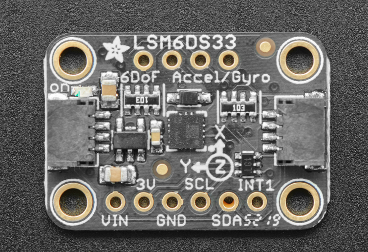
Pinout Diagrams
Official Adafruit Pinout Images
Basic Wiring Examples
I2C Connection (Recommended)
Arduino Uno Connection
LSM6DS33       Arduino Uno
--------       -----------
VIN       →    5V or 3.3V
GND       →    GND
SDA       →    A4 (SDA)
SCL       →    A5 (SCL)

Note: Built-in pull-up resistors included
Raspberry Pi Pico Connection
LSM6DS33       Pico
--------       ----
VIN       →    3V3
GND       →    GND
SDA       →    GP4 (I2C0 SDA)
SCL       →    GP5 (I2C0 SCL)

Note: Built-in pull-up resistors included
ESP32 Connection
LSM6DS33       ESP32
--------       -----
VIN       →    3.3V
GND       →    GND
SDA       →    GPIO21 (SDA)
SCL       →    GPIO22 (SCL)

Note: ESP32 has built-in I2C pull-up resistors
STEMMA QT Plug-and-Play Connection
Simply connect STEMMA QT cable between:
- LSM6DS33 STEMMA QT connector
- Microcontroller STEMMA QT connector

No additional wiring required!
Compatible with: QT Py, Feather, Metro, etc.
SPI Connection (Advanced)
LSM6DS33       Arduino Uno
--------       -----------
VIN       →    5V or 3.3V
GND       →    GND
SCK       →    Pin 13 (SCK)
MOSI      →    Pin 11 (MOSI)
MISO      →    Pin 12 (MISO)
CS        →    Pin 10 (or any digital pin)

Note: SPI mode for high-speed applications
Interrupt Connections (Optional)
LSM6DS33       Arduino
--------       -------
INT1      →    Pin 2 (interrupt-capable pin)
INT2      →    Pin 3 (interrupt-capable pin)

Use for motion detection, tap detection, etc.
Programming Examples
Arduino - Basic Reading
#include <Adafruit_LSM6DS33.h>

Adafruit_LSM6DS33 lsm6ds33;

void setup() {
  Serial.begin(115200);
  while (!Serial);

  if (!lsm6ds33.begin_I2C()) {
    Serial.println("Failed to find LSM6DS33 chip");
    while (1);
  }

  Serial.println("LSM6DS33 Found!");

  // Set accelerometer range (2G, 4G, 8G, 16G)
  lsm6ds33.setAccelRange(LSM6DS_ACCEL_RANGE_2_G);

  // Set gyroscope range (125, 250, 500, 1000, 2000 DPS)
  lsm6ds33.setGyroRange(LSM6DS_GYRO_RANGE_250_DPS);

  // Set data rate (12.5, 26, 52, 104, 208, 416, 833, 1666 Hz)
  lsm6ds33.setAccelDataRate(LSM6DS_RATE_104_HZ);
  lsm6ds33.setGyroDataRate(LSM6DS_RATE_104_HZ);
}

void loop() {
  sensors_event_t accel;
  sensors_event_t gyro;
  sensors_event_t temp;

  lsm6ds33.getEvent(&accel, &gyro, &temp);

  Serial.print("Accelerometer (m/s²): ");
  Serial.print("X: "); Serial.print(accel.acceleration.x, 2);
  Serial.print(", Y: "); Serial.print(accel.acceleration.y, 2);
  Serial.print(", Z: "); Serial.print(accel.acceleration.z, 2);
  Serial.println();

  Serial.print("Gyroscope (°/s): ");
  Serial.print("X: "); Serial.print(gyro.gyro.x, 2);
  Serial.print(", Y: "); Serial.print(gyro.gyro.y, 2);
  Serial.print(", Z: "); Serial.print(gyro.gyro.z, 2);
  Serial.println();

  Serial.print("Temperature: ");
  Serial.print(temp.temperature);
  Serial.println(" °C");

  Serial.println("---");
  delay(500);
}
Arduino - Motion Detection
#include <Adafruit_LSM6DS33.h>

Adafruit_LSM6DS33 lsm6ds33;

void setup() {
  Serial.begin(115200);
  while (!Serial);

  if (!lsm6ds33.begin_I2C()) {
    Serial.println("Failed to find LSM6DS33 chip");
    while (1);
  }

  Serial.println("LSM6DS33 Motion Detection");

  lsm6ds33.setAccelRange(LSM6DS_ACCEL_RANGE_2_G);
  lsm6ds33.setAccelDataRate(LSM6DS_RATE_104_HZ);
}

void loop() {
  sensors_event_t accel;
  sensors_event_t gyro;
  sensors_event_t temp;

  lsm6ds33.getEvent(&accel, &gyro, &temp);

  // Calculate total acceleration magnitude
  float totalAccel = sqrt(
    accel.acceleration.x * accel.acceleration.x +
    accel.acceleration.y * accel.acceleration.y +
    accel.acceleration.z * accel.acceleration.z
  );

  // Detect motion (deviation from 1G gravity)
  float motionThreshold = 2.0;  // Adjust sensitivity
  if (abs(totalAccel - 9.8) > motionThreshold) {
    Serial.println("MOTION DETECTED!");
    Serial.print("Total acceleration: ");
    Serial.print(totalAccel, 2);
    Serial.println(" m/s²");
  }

  // Detect rotation
  float rotationThreshold = 50.0;  // degrees/second
  if (abs(gyro.gyro.x) > rotationThreshold ||
      abs(gyro.gyro.y) > rotationThreshold ||
      abs(gyro.gyro.z) > rotationThreshold) {
    Serial.println("ROTATION DETECTED!");
    Serial.print("Gyro: X="); Serial.print(gyro.gyro.x, 1);
    Serial.print(", Y="); Serial.print(gyro.gyro.y, 1);
    Serial.print(", Z="); Serial.print(gyro.gyro.z, 1);
    Serial.println(" °/s");
  }

  delay(100);
}
CircuitPython - Basic Reading
import time
import board
import busio
import adafruit_lsm6ds.lsm6ds33

# Initialize I2C
i2c = busio.I2C(board.SCL, board.SDA)
sensor = adafruit_lsm6ds.lsm6ds33.LSM6DS33(i2c)

# Configure sensor
sensor.accelerometer_range = adafruit_lsm6ds.AccelRange.RANGE_2G
sensor.gyro_range = adafruit_lsm6ds.GyroRange.RANGE_250_DPS
sensor.accelerometer_data_rate = adafruit_lsm6ds.Rate.RATE_104_HZ
sensor.gyro_data_rate = adafruit_lsm6ds.Rate.RATE_104_HZ

print("LSM6DS33 6-DoF IMU Test")

while True:
    accel_x, accel_y, accel_z = sensor.acceleration
    gyro_x, gyro_y, gyro_z = sensor.gyro

    print(f"Acceleration (m/s²): X={accel_x:.2f}, Y={accel_y:.2f}, Z={accel_z:.2f}")
    print(f"Gyroscope (°/s): X={gyro_x:.2f}, Y={gyro_y:.2f}, Z={gyro_z:.2f}")
    print(f"Temperature: {sensor.temperature:.1f} °C")
    print("---")

    time.sleep(0.5)
CircuitPython - Tilt Detection
import time
import board
import busio
import adafruit_lsm6ds.lsm6ds33
import math

i2c = busio.I2C(board.SCL, board.SDA)
sensor = adafruit_lsm6ds.lsm6ds33.LSM6DS33(i2c)

def calculate_tilt_angles(accel_x, accel_y, accel_z):
    """Calculate roll and pitch angles from accelerometer data"""
    roll = math.atan2(accel_y, accel_z) * 180 / math.pi
    pitch = math.atan2(-accel_x, math.sqrt(accel_y**2 + accel_z**2)) * 180 / math.pi
    return roll, pitch

print("LSM6DS33 Tilt Detection")

while True:
    accel_x, accel_y, accel_z = sensor.acceleration

    roll, pitch = calculate_tilt_angles(accel_x, accel_y, accel_z)

    print(f"Tilt - Roll: {roll:.1f}°, Pitch: {pitch:.1f}°")

    # Detect significant tilt
    if abs(roll) > 30 or abs(pitch) > 30:
        print("SIGNIFICANT TILT DETECTED!")

    time.sleep(0.2)
Pinout and Connections
STEMMA QT Connector
| Pin | Signal | Description |
|---|---|---|
| 1 | GND | Ground |
| 2 | VCC | 3.3V Power |
| 3 | SDA | I²C Data |
| 4 | SCL | I²C Clock |
Breakout Pins
| Pin | Signal | Description |
|---|---|---|
| VIN | VCC | Power input (3.0V to 5.5V) |
| GND | GND | Ground |
| SCL | SCL | I²C Clock / SPI Clock |
| SDA | SDA | I²C Data / SPI MOSI |
| SDO | SDO | SPI MISO / I²C Address Select |
| CS | CS | SPI Chip Select |
| INT1 | INT1 | Interrupt 1 output |
| INT2 | INT2 | Interrupt 2 output |
Applications
Robotics and Automation
- Robot balance and stabilization
- Drone flight control systems
- Autonomous vehicle navigation
- Robotic arm orientation tracking
- Mobile robot dead reckoning
Motion Tracking
- Human activity monitoring
- Sports performance analysis
- Gaming motion controllers
- Virtual reality tracking
- Gesture recognition systems
Industrial Applications
- Machine vibration monitoring
- Equipment tilt detection
- Platform stabilization
- Safety monitoring systems
- Precision positioning
Programming and Integration
Arduino Library Support
#include <Adafruit_LSM6DS33.h>

Adafruit_LSM6DS33 lsm6ds33;

void setup() {
  Serial.begin(115200);

  if (!lsm6ds33.begin_I2C()) {
    Serial.println("Failed to find LSM6DS33 chip");
    while (1) { delay(10); }
  }

  Serial.println("LSM6DS33 Found!");
}

void loop() {
  sensors_event_t accel;
  sensors_event_t gyro;
  sensors_event_t temp;

  lsm6ds33.getEvent(&accel, &gyro, &temp);

  Serial.print("Accel X: "); Serial.print(accel.acceleration.x);
  Serial.print(" Y: "); Serial.print(accel.acceleration.y);
  Serial.print(" Z: "); Serial.println(accel.acceleration.z);

  Serial.print("Gyro X: "); Serial.print(gyro.gyro.x);
  Serial.print(" Y: "); Serial.print(gyro.gyro.y);
  Serial.print(" Z: "); Serial.println(gyro.gyro.z);

  delay(100);
}
Configuration Options
- Accelerometer range: ±2g to ±16g
- Gyroscope range: ±125°/s to ±2000°/s
- Output data rate: 12.5Hz to 1.6kHz
- High-pass filtering: Configurable cutoff frequencies
- Interrupt configuration: Motion detection, tap detection, free-fall
Advanced Features
Motion Detection
- Tap detection: Single and double tap recognition
- Free-fall detection: Configurable threshold and duration
- Wake-up detection: Motion-based wake from sleep
- Activity/inactivity: Automatic activity classification
- 6D/4D orientation: Device orientation detection
Data Management
- FIFO buffer: Up to 4KB internal buffer
- Timestamp: Internal timestamp for data synchronization
- Batch mode: Low-power data collection
- Interrupt routing: Flexible interrupt pin assignment
Calibration and Setup
Basic Calibration
- Accelerometer offset: Measure in all six orientations
- Gyroscope bias: Measure when stationary
- Temperature compensation: Account for temperature effects
- Cross-axis sensitivity: Minimize coupling between axes
Performance Optimization
- Stable mounting: Secure mechanical attachment
- Temperature control: Maintain stable operating temperature
- Vibration isolation: Minimize external vibrations
- Power supply: Use clean, stable power source
Design Considerations
Power Management
- Low power modes: Multiple sleep and standby modes
- Power consumption: Optimize for battery-powered applications
- Wake-up sources: Configure interrupt-based wake-up
- Supply decoupling: Proper power supply filtering
Signal Processing
- Digital filtering: Built-in anti-aliasing filters
- Data fusion: Combine accelerometer and gyroscope data
- Coordinate transformation: Convert between reference frames
- Noise reduction: Implement appropriate filtering algorithms
Troubleshooting
Common Issues
- Communication errors: Check I²C/SPI connections and addresses
- Incorrect readings: Verify sensor orientation and calibration
- High noise: Check mechanical mounting and power supply
- Interrupt issues: Verify interrupt configuration and routing
Performance Tips
- Proper calibration: Follow calibration procedures carefully
- Mechanical design: Ensure rigid mounting and proper orientation
- Software filtering: Implement appropriate digital filters
- Environmental control: Minimize temperature variations
Included Components
- LSM6DS33 breakout board with STEMMA QT connectors
- Header pins for breadboard use
- Mounting holes for secure installation
- Arduino library and example code
Storage Information
- Location: Cabinet 3, Bin 28
- Quantity: 2 units
- Condition: New, unused
- Status: Discontinued, replaced by LSM6DS3TR-C