Important NoteThis entire repo was AI created - including all of the data within. The intent was to A) help me with my personal electronics inventory; and B) see how I could use AI to make that process a bit easier. DO NOT TRUST!
Arduino Uno Rev3
Overview
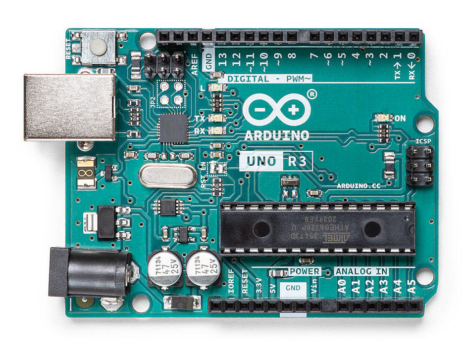
The Arduino Uno Rev3 is a microcontroller board based on the ATmega328P. It has 14 digital input/output pins (of which 6 can be used as PWM outputs), 6 analog inputs, a 16 MHz ceramic resonator, a USB connection, a power jack, an ICSP header and a reset button. It contains everything needed to support the microcontroller; simply connect it to a computer with a USB cable or power it with an AC-to-DC adapter or battery to get started.
“Uno” means one in Italian and was chosen to mark the release of Arduino Software (IDE) 1.0. The Uno board and version 1.0 of Arduino Software (IDE) were the reference versions of Arduino, now evolved to newer releases. The Uno board is the first in a series of USB Arduino boards, and the reference model for the Arduino platform.
Specifications
- Microcontroller: ATmega328P
- Operating Voltage: 5V
- Input Voltage (recommended): 7-12V
- Input Voltage (limit): 6-20V
- Digital I/O Pins: 14 (of which 6 provide PWM output)
- PWM Digital I/O Pins: 6
- Analog Input Pins: 6
- DC Current per I/O Pin: 20 mA
- DC Current for 3.3V Pin: 50 mA
- Flash Memory: 32 KB (ATmega328P) of which 0.5 KB used by bootloader
- SRAM: 2 KB (ATmega328P)
- EEPROM: 1 KB (ATmega328P)
- Clock Speed: 16 MHz
- LED_BUILTIN: 13
- Length: 68.6 mm
- Width: 53.4 mm
- Weight: 25 g
Key Features
Microcontroller Core
- ATmega328P: 8-bit AVR microcontroller with Harvard architecture
- 16 MHz Clock: Crystal oscillator for precise timing
- 32KB Flash: Program storage with bootloader
- 2KB SRAM: Runtime memory for variables
- 1KB EEPROM: Non-volatile data storage
Input/Output Capabilities
- 14 Digital Pins: Configurable as input or output
- 6 PWM Outputs: 8-bit PWM on pins 3, 5, 6, 9, 10, 11
- 6 Analog Inputs: 10-bit ADC resolution (1024 values)
- Built-in LED: Connected to pin 13 for testing
Communication Interfaces
- USB: Native USB connectivity for programming and serial communication
- UART: Hardware serial on pins 0 (RX) and 1 (TX)
- SPI: Serial Peripheral Interface on pins 10-13
- I2C/TWI: Two-wire interface on pins A4 (SDA) and A5 (SCL)
Power Management
- Multiple Power Sources: USB, DC jack, or VIN pin
- Automatic Source Selection: Seamless switching between power sources
- Voltage Regulation: Onboard 5V and 3.3V regulators
- Polyfuse Protection: USB overcurrent protection
Pin Configuration
Digital Pins (0-13)
- Pin 0 (RX): Serial receive, also digital I/O
- Pin 1 (TX): Serial transmit, also digital I/O
- Pins 2-3: External interrupt pins
- Pins 3, 5, 6, 9, 10, 11: PWM output pins
- Pin 13: Built-in LED and SPI clock
- Pins 10-13: SPI interface (SS, MOSI, MISO, SCK)
Analog Pins (A0-A5)
- A0-A5: 10-bit analog inputs (0-1023 values)
- A4 (SDA): I2C data line
- A5 (SCL): I2C clock line
- AREF: Analog reference voltage input
Power Pins
- VIN: Input voltage when using external power
- 5V: Regulated 5V output
- 3V3: 3.3V output (50mA max)
- GND: Ground pins
- IOREF: I/O reference voltage (5V)
Programming and Development
Arduino IDE Support
- Native Support: Full compatibility with Arduino IDE
- Extensive Libraries: Thousands of available libraries
- Community Support: Large user community and documentation
- Easy Programming: Simple upload via USB
Bootloader
- Pre-installed: Arduino bootloader for easy programming
- USB Programming: No external programmer needed
- STK500 Compatible: Standard Arduino programming protocol
- Auto-reset: Automatic reset for programming
Applications
Education and Learning
- Beginner Friendly: Ideal first microcontroller board
- STEM Education: Perfect for teaching electronics and programming
- Prototyping: Quick project development and testing
- Maker Projects: DIY electronics and automation
Project Categories
- Home Automation: Light control, sensor monitoring
- Robotics: Motor control, sensor integration
- IoT Projects: Data logging, remote monitoring
- Interactive Art: LED displays, sound projects
Memory Organization
Flash Memory (32KB)
- Program Storage: User sketches and libraries
- Bootloader: 0.5KB reserved for Arduino bootloader
- Available Space: 31.5KB for user programs
- Non-volatile: Retains programs when powered off
SRAM (2KB)
- Variable Storage: Runtime variables and arrays
- Stack Space: Function calls and local variables
- Volatile: Lost when power is removed
- Shared Resource: Used by all program components
EEPROM (1KB)
- Persistent Storage: Data that survives power cycles
- Configuration: Settings and calibration data
- User Accessible: Can be read/written by sketches
- Limited Writes: ~100,000 write cycles per location
Communication Protocols
Serial Communication
- Hardware UART: Pins 0 (RX) and 1 (TX)
- USB Serial: Virtual COM port over USB
- Baud Rates: Up to 115200 bps
- Software Serial: Additional serial ports on any digital pins
SPI Communication
- Hardware SPI: Pins 10 (SS), 11 (MOSI), 12 (MISO), 13 (SCK)
- High Speed: Fast synchronous communication
- Multiple Devices: Chip select for device selection
- Standard Protocol: Compatible with many sensors and modules
I2C/TWI Communication
- Hardware I2C: Pins A4 (SDA) and A5 (SCL)
- Two-wire Interface: Clock and data lines
- Multiple Devices: Address-based device selection
- Pull-up Resistors: May need external pull-ups for long distances
Power Specifications
Input Power
- USB Power: 5V from USB connection (500mA max)
- DC Jack: 2.1mm center-positive plug (7-12V recommended)
- VIN Pin: Direct connection to voltage regulator input
- Automatic Selection: Board automatically selects power source
Output Power
- 5V Rail: Regulated 5V output for shields and sensors
- 3.3V Rail: 3.3V output with 50mA maximum current
- I/O Current: 20mA maximum per pin, 200mA total
- Power LED: Green LED indicates board is powered
Shield Compatibility
Standard Shields
- Arduino Shields: Compatible with official Arduino shields
- Third-party Shields: Works with most Uno-compatible shields
- Stacking: Multiple shields can be stacked
- Pin Mapping: Standard Arduino pin layout
Popular Shield Types
- Motor Shields: DC motor and stepper motor control
- Sensor Shields: Easy sensor connections
- Display Shields: LCD and OLED displays
- Communication Shields: WiFi, Bluetooth, Ethernet
Getting Started
Basic Setup
- Install Arduino IDE: Download from arduino.cc
- Connect USB Cable: Use USB A to B cable
- Select Board: Choose “Arduino Uno” in IDE
- Select Port: Choose correct COM port
- Upload Sketch: Start with Blink example
First Projects
- Blink LED: Control built-in LED on pin 13
- Serial Communication: Send data to computer
- Analog Reading: Read sensor values
- Digital I/O: Control LEDs and read buttons
Package Contents
- 1x Arduino Uno Rev3 board
- Documentation and getting started guide
- Stickers and promotional materials
Important Notes
- Voltage Levels: 5V logic, not directly compatible with 3.3V devices
- Current Limits: Don’t exceed 20mA per pin or 200mA total
- Power Considerations: Check power requirements for connected devices
- Shield Compatibility: Verify shield compatibility before use
Advantages
- Industry Standard: Most popular Arduino board
- Extensive Support: Large community and documentation
- Shield Ecosystem: Hundreds of compatible shields
- Beginner Friendly: Easy to learn and use
- Reliable: Proven design with excellent track record
Pinout Diagram
                    Arduino Uno Rev3 Pinout

                    +-----+
         +----------| USB |----------+
         |          +-----+          |
         | [ ]D13/SCK        MISO/D12[ ] |
         | [ ]3.3V           MOSI/D11[ ]~|
         | [ ]V.ref     ___    SS/D10[ ]~|
         | [ ]A0       / N \       D9[ ]~|
         | [ ]A1      /  A  \      D8[ ] |
         | [ ]A2      \  N  /      D7[ ] |
         | [ ]A3       \_O_/       D6[ ]~|
         | [ ]A4/SDA              D5[ ]~|
         | [ ]A5/SCL              D4[ ] |
         | [ ]A6              INT1/D3[ ]~|
         | [ ]A7              INT0/D2[ ] |
         | [ ]5V                  GND[ ] |
         | [ ]RST                 RST[ ] |
         | [ ]GND   +5V   +3V3    TX1[ ] |
         | [ ]VIN   [ ]   [ ]     RX0[ ] |
         |          [ ]                  |
         |          GND                  |
         +-------------------------------+

Legend: [ ] = Pin, ~ = PWM capable, SDA/SCL = I2C
Basic Wiring Examples
LED Blink Circuit
Arduino Pin 13 → LED Anode (long leg)
LED Cathode (short leg) → 220Ω Resistor → GND

Note: Pin 13 has built-in LED, external LED optional
Button Input Circuit
5V → 10kΩ Pull-up Resistor → Arduino Pin 2
Arduino Pin 2 → Button → GND

Code: digitalRead(2) returns HIGH when not pressed, LOW when pressed
Analog Sensor Reading
5V → Sensor VCC
GND → Sensor GND
Sensor Output → Arduino Pin A0

Code: analogRead(A0) returns 0-1023 (0-5V)
I2C Device Connection
Arduino 5V → Device VCC
Arduino GND → Device GND
Arduino Pin A4 (SDA) → Device SDA
Arduino Pin A5 (SCL) → Device SCL
Add 4.7kΩ pull-up resistors on SDA and SCL lines
SPI Device Connection
Arduino 5V → Device VCC
Arduino GND → Device GND
Arduino Pin 13 (SCK) → Device SCK
Arduino Pin 12 (MISO) → Device MISO
Arduino Pin 11 (MOSI) → Device MOSI
Arduino Pin 10 (SS) → Device CS/SS
Programming Setup Guide
Arduino IDE Setup
- Download Arduino IDE from arduino.cc
- Install USB drivers (usually automatic)
- Connect Arduino via USB cable
- Select “Arduino Uno” from Tools → Board
- Select correct COM port from Tools → Port
- Upload “Blink” example to test
First Program Example
// Basic LED blink program
void setup() {
  pinMode(13, OUTPUT);  // Set pin 13 as output
}

void loop() {
  digitalWrite(13, HIGH);  // Turn LED on
  delay(1000);             // Wait 1 second
  digitalWrite(13, LOW);   // Turn LED off
  delay(1000);             // Wait 1 second
}
Recommended Accessories
- USB cable (Type A to Type B)
- DC power adapter (9V, center positive)
- Breadboard and jumper wires
- Basic electronic components (LEDs, resistors, sensors)
- Arduino shields for expanded functionality