Important NoteThis entire repo was AI created - including all of the data within. The intent was to A) help me with my personal electronics inventory; and B) see how I could use AI to make that process a bit easier. DO NOT TRUST!
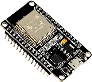
ESP-WROOM-32 ESP32 ESP-32S Development Board
Details
- Location: Cabinet-1, Bin 31
- Category: Development Boards
- Type: ESP32 Development Board
- Microcontroller: ESP32 (Dual Xtensa LX6 @ 240MHz)
- Brand: AITRIP
- Part Number: B07WCG1PLV
- Quantity: 2
- Product URL: https://a.co/d/ciKueeW
Description
The ESP-WROOM-32 ESP32 ESP-32S Development Board is a 2.4GHz dual-mode WiFi + Bluetooth development board featuring dual cores microcontroller processor integrated with antenna RF AMP filter. It supports AP, STA, and AP+STA modes with ultra-low power consumption and is compatible with Arduino IDE.
Specifications
- Microcontroller: ESP32 dual-core Xtensa LX6 @ up to 240MHz
- Memory: 520KB SRAM, 4MB Flash
- WiFi: 802.11 b/g/n with integrated antenna
- Bluetooth: Bluetooth Classic and BLE (Bluetooth Low Energy)
- GPIO Pins: 30 total programmable pins
- ADC: 12x 12-bit analog inputs
- DAC: 2x 8-bit digital-to-analog converters
- Touch: Capacitive touch GPIO pins
- Peripherals: I2C, SPI, UART, I2S interfaces
- USB: USB-Micro connector for programming and power
- Power: 3.3V operating voltage
- Antenna: Integrated PCB antenna
Dimensions
- Board Size: 55mm x 28mm (2.17” x 1.10”)
- Weight: ~10g
- Form Factor: Standard ESP32 DevKit compatible
Image
Features
- ESP-WROOM-32 Module: Certified wireless module with 4MB Flash
- Dual-Core Performance: Two Xtensa LX6 cores for multitasking
- Dual-Mode Connectivity: WiFi 802.11 b/g/n and Bluetooth Classic/LE
- Integrated Antenna: PCB antenna with RF amplifier and filter
- Multiple Operating Modes: AP (Access Point), STA (Station), AP+STA
- Rich Peripherals: Multiple communication interfaces and GPIO pins
- Touch Interface: Capacitive touch-enabled GPIO pins
- Low Power: Ultra-low power consumption with multiple sleep modes
- Arduino Compatible: Works with Arduino IDE and ESP-IDF
Connectivity
- WiFi: 802.11 b/g/n 2.4GHz with WPA/WPA2 security
- Bluetooth: Bluetooth Classic and Low Energy support
- Antenna: Integrated PCB antenna with RF amplifier
- Range: Good RF performance for IoT applications
Programming Support
- Arduino IDE: Full Arduino support with ESP32 core
- ESP-IDF: Official Espressif development framework
- PlatformIO: Professional IDE support
- MicroPython: Community support available
- LWIP Protocol: TCP/IP stack support
- FreeRTOS: Real-time operating system support
Power Management
- Operating Voltage: 3.3V
- Input Voltage: 5V via USB-Micro
- Power Consumption: Ultra-low power with sleep modes
- Sleep Modes: Multiple low-power modes available
Development Features
- Boot/Reset Buttons: Easy programming and reset functionality
- LED Indicators: Power and user-programmable LEDs
- Pin Headers: Standard 2.54mm pitch for breadboard compatibility
- Compact Design: Optimized for prototyping and development
Supported Protocols
- LWIP: Lightweight TCP/IP stack
- FreeRTOS: Real-time operating system
- WiFi Protocols: WPA/WPA2 security
- Bluetooth Protocols: Classic and Low Energy profiles
Pinout Diagram
                    ESP32 Development Board Pinout

                    +-----+
         +----------| USB |----------+
         |          +-----+          |
         | [ ]3V3                EN[ ] |
         | [ ]GND               VP[ ] |
         | [ ]D15               VN[ ] |
         | [ ]D2                D34[ ] |
         | [ ]D4                D35[ ] |
         | [ ]D16               D32[ ] |
         | [ ]D17               D33[ ] |
         | [ ]D5                D25[ ] |
         | [ ]D18               D26[ ] |
         | [ ]D19               D27[ ] |
         | [ ]GND               D14[ ] |
         | [ ]D21               D12[ ] |
         | [ ]RX                D13[ ] |
         | [ ]TX                GND[ ] |
         | [ ]D22               VIN[ ] |
         | [ ]D23                     |
         |                           |
         |    [BOOT]  [EN]            |
         +---------------------------+

Note: GPIO pins are 3.3V logic level only
Basic Wiring Examples
LED Blink Circuit
ESP32 GPIO2 → LED Anode (long leg)
LED Cathode (short leg) → 220Ω Resistor → ESP32 GND

Note: GPIO2 has built-in LED on most ESP32 boards
Button Input Circuit
ESP32 3V3 → 10kΩ Pull-up Resistor → ESP32 GPIO0
ESP32 GPIO0 → Button → ESP32 GND

Code: digitalRead(0) returns HIGH when not pressed, LOW when pressed
I2C Device Connection
ESP32 3V3 → Device VCC
ESP32 GND → Device GND
ESP32 GPIO21 (SDA) → Device SDA
ESP32 GPIO22 (SCL) → Device SCL
Add 4.7kΩ pull-up resistors on SDA and SCL lines
SPI Device Connection
ESP32 3V3 → Device VCC
ESP32 GND → Device GND
ESP32 GPIO18 (SCK) → Device SCK
ESP32 GPIO19 (MISO) → Device MISO
ESP32 GPIO23 (MOSI) → Device MOSI
ESP32 GPIO5 (CS) → Device CS/SS
Analog Reading
Sensor Output → ESP32 GPIO36 (VP), GPIO39 (VN), or other ADC pins
Code: analogRead(A0) returns 0-4095 (0-3.3V)
Programming Setup Guide
Arduino IDE Setup
- Install Arduino IDE 1.8.13 or later
- Add ESP32 board package URL in preferences:
https://dl.espressif.com/dl/package_esp32_index.json - Install “ESP32 by Espressif Systems” from Board Manager
- Select “ESP32 Dev Module” from Tools → Board
- Select correct COM port from Tools → Port
- Upload code via USB
ESP-IDF Setup
- Install ESP-IDF development framework
- Set up toolchain and environment variables
- Use
idf.pycommands for building and flashing - More advanced development with full ESP32 features
Programming Examples
Arduino WiFi Connection
#include <WiFi.h>

const char* ssid = "your_wifi_name";
const char* password = "your_wifi_password";

void setup() {
  Serial.begin(115200);
  WiFi.begin(ssid, password);

  while (WiFi.status() != WL_CONNECTED) {
    delay(1000);
    Serial.println("Connecting to WiFi...");
  }

  Serial.println("Connected to WiFi");
  Serial.print("IP address: ");
  Serial.println(WiFi.localIP());
}

void loop() {
  // Your code here
}
Arduino Bluetooth Example
#include "BluetoothSerial.h"

BluetoothSerial SerialBT;

void setup() {
  Serial.begin(115200);
  SerialBT.begin("ESP32test"); // Bluetooth device name
  Serial.println("The device started, now you can pair it with bluetooth!");
}

void loop() {
  if (Serial.available()) {
    SerialBT.write(Serial.read());
  }
  if (SerialBT.available()) {
    Serial.write(SerialBT.read());
  }
  delay(20);
}
Arduino Web Server Example
#include <WiFi.h>
#include <WebServer.h>

const char* ssid = "your_wifi_name";
const char* password = "your_wifi_password";

WebServer server(80);

void handleRoot() {
  server.send(200, "text/html", "<h1>ESP32 Web Server</h1>");
}

void setup() {
  Serial.begin(115200);
  WiFi.begin(ssid, password);

  while (WiFi.status() != WL_CONNECTED) {
    delay(1000);
    Serial.println("Connecting to WiFi...");
  }

  server.on("/", handleRoot);
  server.begin();
  Serial.println("HTTP server started");
}

void loop() {
  server.handleClient();
}
Important Notes
Voltage Levels
- GPIO Voltage: 3.3V logic level only
- Not 5V Tolerant: Do not connect 5V signals directly
- Power Supply: 3.3V regulated output available
- Input Voltage: 5V via USB or VIN pin
GPIO Limitations
- Input Only: GPIO34, GPIO35, GPIO36, GPIO39 are input only
- Boot Pins: GPIO0, GPIO2, GPIO12, GPIO15 affect boot mode
- ADC2: Cannot use ADC2 pins when WiFi is active
- Touch Pins: GPIO0, GPIO2, GPIO4, GPIO12-15, GPIO27, GPIO32-33
Tags
microcontroller, esp32, esp-wroom-32, wifi, bluetooth-le, bluetooth-classic, aitrip, arduino, esp-idf, dual-core, iot, development-board
Notes
This development board is perfect for IoT projects requiring WiFi and Bluetooth connectivity. The ESP32 offers excellent performance with dual-core processing and comprehensive wireless capabilities. The integrated antenna eliminates the need for external antenna connections. Ideal for Arduino IDE development and prototyping of wireless applications. Important: All GPIO pins are 3.3V logic level only - not 5V tolerant!