Important NoteThis entire repo was AI created - including all of the data within. The intent was to A) help me with my personal electronics inventory; and B) see how I could use AI to make that process a bit easier. DO NOT TRUST!
FNRSI LCR-P1 Transistor Meter
Overview
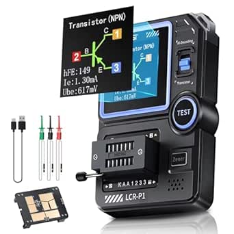
The FNRSI LCR-P1 is a multifunctional electronic component tester capable of analyzing and measuring various semiconductor components including transistors, diodes, capacitors, inductors, and resistors. This professional-grade instrument features intelligent component recognition with one-button operation and includes advanced features like SMD testing and infrared signal decoding.
Key Features
Component Testing Capabilities
- Transistors: Automatic detection of NPN/PNP bipolar transistors with β measurement (10-600 range)
- Field-Effect Transistors: Supports JFET, IGBT, and MOSFET testing
- Diodes: Forward voltage drop measurement (<4.5V)
- Voltage Regulator Diodes: Zener voltage testing (0.01-4.5V, 0.01-32V)
- Passive Components: Resistance (0.010-50MΩ), Capacitance (25pF-100mF), Inductance (10uH-1000uH)
Advanced Features
- SMD Testing: Dedicated adapter for surface-mount device testing
- Anti-burn Protection: Built-in safety mechanism prevents component damage
- NEC Infrared Decoding: Remote control signal analysis capability
- Data Export: USB connectivity for PC data transfer and Excel export
- Replaceable Test Boards: Modular design for different testing scenarios
Hardware Design
- Display: Color LCD screen with backlight for easy reading
- Power: 300mAh rechargeable battery for portable operation
- Test Socket: Zero insertion force (ZIF) socket for easy component insertion
- Build Quality: Professional-level construction with replaceable components
Testing Specifications
| Parameter | Range | Notes |
|---|---|---|
| Resistance | 0.010Ω - 50MΩ | Wide range for various resistor types |
| Capacitance | 25pF - 100mF | Covers most common capacitor values |
| Inductance | 10µH - 1000µH | Suitable for coils and inductors |
| Transistor β | 10 - 600 | Current gain measurement |
| Diode Vf | < 4.5V | Forward voltage drop |
| Zener Voltage | 0.01V - 32V | Voltage regulator testing |
Usage Instructions
- Power On: Press power button to activate the device
- Component Insertion: Place component in ZIF socket or use test clips
- Auto-Test: Press test button for automatic component identification
- Results: View component type, pinout, and measured values on display
- Data Export: Connect via USB to transfer results to PC
SMD Testing
The LCR-P1 includes a specialized SMD adapter that replaces the standard ZIF socket:
- Remove the ZIF socket module by pulling upward
- Install the SMD adapter in its place
- Place SMD components on the test platform
- Use the same one-button testing procedure
Applications
- Component Sorting: Organize loose components by type and value
- Quality Control: Verify component specifications before use
- Circuit Debugging: Test components in-circuit (power off)
- Education: Learn component characteristics and behavior
- Repair Work: Identify faulty components in electronic devices
Location
Cabinet: 4
Bin: 7
Quantity: 1
Purchase Information
- Source: Amazon
- Price: 39.99, 25% savings)
- Purchase Date: January 13, 2025
- Product URL: Amazon Link
Notes
This is an excellent value for a multifunctional component tester. The device provides professional-level testing capabilities at a fraction of the cost of traditional LCR meters. The SMD testing capability and data export features make it particularly useful for modern electronics work.
The anti-burn protection and one-button operation make it safe and easy to use, while the color display and component pinout diagrams provide clear, informative results.
Pinout/Connection Information
Test Socket Connections
The LCR-P1 uses a Zero Insertion Force (ZIF) socket with the following pin assignments:
- Pin 1: Test Point A (left side when facing display)
- Pin 2: Test Point B (center)
- Pin 3: Test Point C (right side when facing display)
SMD Test Platform
When using the SMD adapter, components are placed directly on the test platform pads which correspond to the same electrical connections as the ZIF socket pins.
USB Connection
- USB Type: Mini-USB connector on side of device
- Function: Data transfer and firmware updates
- Cable: Standard Mini-USB cable (not included)
Circuit Integration Notes
In-Circuit Testing
- IMPORTANT: Always power off circuits before testing components in-circuit
- Can test components with one leg lifted from circuit
- Anti-burn protection helps prevent damage to sensitive components
- Test clips can be used for accessing components without desoldering
Component Handling
- Use anti-static precautions when handling sensitive components
- Clean component leads before testing for accurate readings
- Store in anti-static environment when not in use
Technical Specifications
Measurement Accuracy
- Resistance: ±1% + 3 digits (typical)
- Capacitance: ±2% + 5 digits (typical)
- Inductance: ±3% + 5 digits (typical)
- Voltage: ±1% + 2 digits (typical)
Environmental Specifications
- Operating Temperature: 0°C to 40°C
- Storage Temperature: -10°C to 60°C
- Humidity: 80% RH max (non-condensing)
- Altitude: Up to 2000m
Troubleshooting
Common Issues
- Inaccurate Readings: Clean component leads, check for proper insertion
- No Display: Check battery charge, press power button
- Component Not Detected: Verify component is functional, try different orientation
- SMD Testing Issues: Ensure SMD adapter is properly seated, clean test pads
Calibration
- Device includes internal calibration routines
- Periodic calibration recommended for precision measurements
- Contact manufacturer for calibration procedures if needed
Firmware Updates
The LCR-P1 supports firmware updates via USB connection:
- Download latest firmware from FNRSI website
- Connect device to PC via USB cable
- Follow manufacturer’s update procedure
- Verify firmware version after update
Related Components
- test-equipment - Other testing and measurement tools
- multimeters - Basic electrical measurement tools
- oscilloscopes - Waveform analysis equipment
- component-testers - Similar component testing devices