Important NoteThis entire repo was AI created - including all of the data within. The intent was to A) help me with my personal electronics inventory; and B) see how I could use AI to make that process a bit easier. DO NOT TRUST!
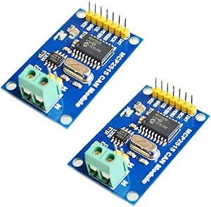
HiLetgo MCP2515 CAN Bus Modules
Details
- Location: Cabinet-2, Bin 12
- Category: Communication Modules
- Brand: HiLetgo
- Model: MCP2515 CAN Bus Module TJA1050
- Quantity: 5 modules (2-pack purchased)
- Amazon URL: https://a.co/d/72fPYxq
Description
HiLetgo MCP2515 CAN Bus modules featuring the MCP2515 CAN controller and TJA1050 CAN transceiver. These modules provide an easy way to add CAN bus communication capability to Arduino and other microcontroller projects, commonly used for automotive OBD-II interfaces and industrial networking applications.
Key Components
MCP2515 CAN Controller
- Function: Stand-alone CAN controller with SPI interface
- Manufacturer: Microchip Technology
- Features:
- Implements CAN 2.0B specification
- SPI interface for microcontroller communication
- Message filtering and buffering
- Error detection and handling
- Low power modes
TJA1050 CAN Transceiver
- Function: High-speed CAN transceiver
- Manufacturer: NXP Semiconductors
- Features:
- Physical layer interface for CAN bus
- Differential signal transmission
- Bus fault protection
- Slope control for EMI reduction
- Wide common-mode range
Image
Technical Specifications
Communication Protocol
- Standard: CAN V2.0B specification
- Speed: Up to 1Mb/s communication speed
- Frame Types: Standard frame, extended frame, remote frame
- Data Field: 0 to 8-byte data field
- Error Detection: CRC, frame check, acknowledgment
Electrical Characteristics
- Power Supply: 5V DC
- Interface: SPI protocol control
- Working Current: 5mA (1µA standby current)
- Termination: 120Ω termination resistors included
- Logic Levels: 5V compatible (3.3V with modifications)
Physical Specifications
- Connector: Standard 0.1” pin headers
- Mounting: Breadboard compatible
- Dimensions: Compact PCB module format
- Indicators: Power LED indicator
Applications
Automotive Projects
- OBD-II Interface: Read diagnostic data from vehicles
- ECU Communication: Interface with engine control units
- Vehicle Networks: Connect to automotive CAN networks
- Diagnostic Tools: Build custom automotive diagnostic equipment
Industrial Applications
- Machine Control: Industrial automation networks
- Sensor Networks: Distributed sensor systems
- Process Control: Manufacturing process monitoring
- Equipment Interface: Connect to industrial CAN devices
Educational Projects
- CAN Protocol Learning: Understand automotive communication
- Network Analysis: Study CAN bus behavior
- Protocol Implementation: Learn industrial networking
- Embedded Systems: Microcontroller communication projects
Arduino Compatibility
Supported Platforms
- Arduino Uno: Direct 5V compatibility
- Arduino Mega: Full pin compatibility
- Arduino Nano: Compact project integration
- ESP32: Requires 3.3V modification (see notes)
- ESP8266: Requires external power and modifications
Required Libraries
- MCP_CAN Library: Arduino library for MCP2515
- CAN-BUS Shield Library: Alternative library option
- Custom Libraries: Various community-developed options
Wiring Connections
- VCC: 5V power supply
- GND: Ground connection
- CS: SPI Chip Select (configurable pin)
- SO: SPI MISO (Master In, Slave Out)
- SI: SPI MOSI (Master Out, Slave In)
- SCK: SPI Clock
- INT: Interrupt pin (optional)
Usage Notes
5V vs 3.3V Operation
- Native: Designed for 5V operation
- 3.3V Modification: Requires hardware modification for ESP32
- Power Requirements: May need external power for some boards
- Logic Level: Consider level shifters for 3.3V systems
CAN Bus Network Requirements
- Termination: 120Ω resistors at both ends of bus
- Twisted Pair: Use proper CAN cable (twisted pair)
- Ground: Common ground reference required
- Length: Consider cable length limitations
Common Applications Setup
- OBD-II: Requires OBD-II connector and proper pinout
- Industrial: Follow CAN bus wiring standards
- Testing: Use CAN bus analyzer for debugging
- Multiple Nodes: Each node needs unique identifier
Programming Examples
Basic CAN Send
#include <mcp_can.h>
#include <SPI.h>

MCP_CAN CAN(10); // CS pin

void setup() {
  if(CAN.begin(MCP_ANY, CAN_500KBPS, MCP_16MHZ) == CAN_OK) {
    Serial.println("MCP2515 Initialized Successfully!");
  }
  CAN.setMode(MCP_NORMAL);
}

void loop() {
  byte data[8] = {0x00, 0x01, 0x02, 0x03, 0x04, 0x05, 0x06, 0x07};
  CAN.sendMsgBuf(0x123, 0, 8, data);
  delay(1000);
}
Basic CAN Receive
void loop() {
  if(CAN_MSGAVAIL == CAN.checkReceive()) {
    CAN.readMsgBuf(&rxId, &len, rxBuf);
    // Process received data
  }
}
Troubleshooting
Common Issues
- No Communication: Check wiring and termination
- Power Problems: Ensure adequate 5V supply
- ESP32 Compatibility: May require hardware modifications
- Library Issues: Use compatible CAN library versions
Debug Tips
- Serial Monitor: Use for debugging messages
- Oscilloscope: Check CAN signal integrity
- Multimeter: Verify power and connections
- CAN Analyzer: Professional debugging tool
Advantages
Design Benefits
- Complete Solution: Controller and transceiver integrated
- Arduino Compatible: Easy integration with popular platforms
- Cost Effective: Affordable CAN bus interface solution
- Compact: Small form factor for embedded projects
Technical Benefits
- Robust Protocol: Industrial-grade communication
- High Speed: Up to 1Mbps data rate
- Error Handling: Built-in error detection and recovery
- Multi-Node: Supports multiple devices on same bus
Limitations
Hardware Limitations
- 5V Design: Not directly compatible with 3.3V systems
- SPI Interface: Requires SPI pins on microcontroller
- External Components: May need additional termination
- Power Consumption: Higher than some alternatives
Software Limitations
- Library Dependency: Requires specific CAN libraries
- Configuration: Needs proper bit timing setup
- Debugging: Limited built-in diagnostic features
- Documentation: Some library documentation gaps
Tags
can-bus, mcp2515, tja1050, automotive, obd2, industrial, communication, hiletgo
Notes
These modules are excellent for learning CAN bus communication and building automotive diagnostic tools. The combination of MCP2515 controller and TJA1050 transceiver provides a complete CAN interface solution. While designed for 5V operation, they can be modified for 3.3V systems with some hardware changes. Popular for OBD-II projects and industrial automation applications.