Important NoteThis entire repo was AI created - including all of the data within. The intent was to A) help me with my personal electronics inventory; and B) see how I could use AI to make that process a bit easier. DO NOT TRUST!
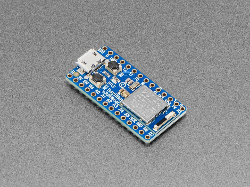
Adafruit ItsyBitsy nRF52840 Express - Bluetooth LE
Details
- Location: Cabinet-1, Bin 28
- Category: Microcontroller Boards
- Type: Bluetooth LE Development Board
- Microcontroller: Nordic nRF52840
- Brand: Adafruit
- Part Number: 4481
- Quantity: 1
- Product URL: https://www.adafruit.com/product/4481
Description
Compact Bluetooth LE development board featuring the Nordic nRF52840 processor in the popular ItsyBitsy form factor. Combines powerful ARM Cortex-M4F processing with built-in Bluetooth LE radio, making it perfect for wireless IoT projects, wearables, and connected devices. Supports both Arduino IDE and CircuitPython for easy development.
Specifications
- Part Number: 4481
- Microcontroller: Nordic nRF52840
- Architecture: 32-bit ARM Cortex-M4F with FPU
- Clock Speed: 64MHz
- Operating Voltage: 3.3V
- Input Voltage: 3.3V-5.5V (via USB or VIN)
- Flash Memory: 1024KB (1MB)
- RAM: 256KB
- QSPI Flash: 2MB for file storage and CircuitPython code
- Dimensions: 36.0mm × 17.6mm × 5.3mm
- Weight: 3.0g
Image
Features
- Bluetooth LE: Built-in 2.4GHz radio with +8dBm output power
- ARM Cortex-M4F: High-performance processor with floating-point unit
- USB Native: Built-in USB support with UF2 bootloader
- CircuitPython: Drag-and-drop programming support
- Arduino Compatible: Full Arduino IDE support
- Compact Size: ItsyBitsy form factor (1.4” × 0.7”)
- Rich I/O: 21 GPIO pins with multiple functions
Bluetooth Capabilities
- Protocol: Bluetooth Low Energy (BLE) 5.0
- Frequency: 2.4GHz ISM band
- Output Power: Up to +8dBm
- Range: Typical 10-100m depending on environment
- Modes: Central and Peripheral operation
- Certification: FCC/IC/TELEC certified module
- Profiles: HID, UART, custom profiles supported
Pin Configuration
- Digital I/O: 21 pins
- Analog Inputs: 6 pins (12-bit ADC)
- PWM Outputs: Up to 12 pins (3 PWM modules × 4 outputs each)
- Communication:
- Hardware SPI, UART, I2C on any pins
- I2S digital audio support
- Special Pins:
- Vhigh output pin for 5V logic devices
- Digital 5 level-shifted output
- Built-in LED (pin 13)
- DotStar RGB LED for status indication
Programming & Software
- Arduino IDE: Full support with Adafruit board package
- CircuitPython: Drag-and-drop Python programming
- UF2 Bootloader: Appears as USB drive for easy programming
- USB Modes: Serial, HID (Keyboard/Mouse), Mass Storage
- Libraries: Extensive Bluetooth and sensor libraries available
- Development: Web-based and desktop IDEs supported
Memory & Storage
- Program Flash: 1MB for application code
- RAM: 256KB for variables and buffers
- QSPI Flash: 2MB for:
- CircuitPython filesystem
- Data logging
- Audio/image files
- User data storage
Power Management
- USB Power: 5V via micro-USB connector
- Battery Power: 3.3V-5.5V via VIN pin or JST connector
- Low Power: Hardware sleep modes for battery operation
- Power LED: Indicates power status
- Current Draw: Varies by application and radio usage
Communication Interfaces
- USB: Native USB 2.0 Full Speed (12 Mbps)
- Bluetooth LE: 2.4GHz wireless communication
- UART: Multiple hardware serial ports
- I2C: Hardware I2C with clock stretching
- SPI: High-speed serial peripheral interface
- I2S: Digital audio interface
Applications
- IoT Devices: Wireless sensors and actuators
- Wearables: Smart clothing and accessories
- Home Automation: Bluetooth-connected home devices
- Health Monitoring: Fitness trackers and medical devices
- Asset Tracking: Location and movement monitoring
- Audio Projects: Bluetooth audio streaming and processing
- Educational: Learning Bluetooth and embedded programming
Advantages
- Wireless Connectivity: Built-in Bluetooth LE radio
- Easy Programming: CircuitPython and Arduino support
- Compact Size: Perfect for space-constrained projects
- Low Power: Optimized for battery-powered applications
- Rich Peripherals: Multiple communication interfaces
- Community Support: Extensive documentation and examples
- Professional Grade: FCC certified for commercial use
Development Tools
- Arduino IDE: Traditional C/C++ development
- CircuitPython: Python-based development
- Visual Studio Code: Advanced IDE with extensions
- Mu Editor: Simple Python editor for beginners
- Web-based IDEs: Browser-based development options
Kit Contents
- ItsyBitsy nRF52840 Express board
- Headers (not pre-soldered)
- Quick start documentation
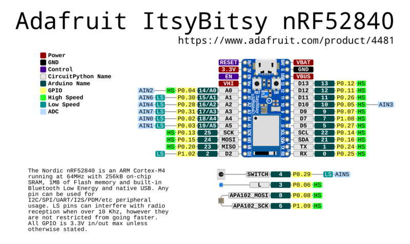
Pinout Diagram
Official Adafruit ItsyBitsy nRF52840 Express Pinout
Basic Wiring Examples
LED Blink Circuit
LED Anode (long leg) → 220Ω Resistor → ItsyBitsy Pin 13
LED Cathode (short leg) → ItsyBitsy GND

Note: Pin 13 has built-in LED, Pin 3 has blue LED
Button Input Circuit
ItsyBitsy 3V → 10kΩ Pull-up Resistor → ItsyBitsy Pin 7
ItsyBitsy Pin 7 → Button → ItsyBitsy GND

Code: pinMode(7, INPUT_PULLUP); digitalRead(7);
I2C Sensor Connection
I2C Sensor VCC → ItsyBitsy 3V
I2C Sensor GND → ItsyBitsy GND
I2C Sensor SDA → ItsyBitsy SDA (requires 2.2kΩ-10kΩ pullup to 3V)
I2C Sensor SCL → ItsyBitsy SCL (requires 2.2kΩ-10kΩ pullup to 3V)

Note: External pullups required for I2C operation
NeoPixel Strip Connection
NeoPixel Strip VCC → ItsyBitsy Vhi (5V when USB powered)
NeoPixel Strip GND → ItsyBitsy GND
NeoPixel Strip DIN → ItsyBitsy Pin 5 (level-shifted to Vhi)

Code: #include <Adafruit_NeoPixel.h>; Adafruit_NeoPixel strip(30, 5);
Servo Motor Connection
Servo Red Wire → ItsyBitsy Vhi (5V)
Servo Black Wire → ItsyBitsy GND
Servo White Wire → ItsyBitsy Pin 9 (PWM capable)

Code: #include <Servo.h>; Servo myservo; myservo.attach(9);
Battery Power Connection
3.7V LiPo Battery + → ItsyBitsy BAT
3.7V LiPo Battery - → ItsyBitsy GND

Note: Automatic switching between USB and battery power
UART Communication
Device TX → ItsyBitsy Pin 0 (RX)
Device RX → ItsyBitsy Pin 1 (TX)
Device VCC → ItsyBitsy 3V
Device GND → ItsyBitsy GND

Code: Serial1.begin(9600); // Hardware UART on pins 0,1
Programming Setup Guide
Arduino IDE Setup
- Install Arduino IDE 1.8.19 or later
- Add Adafruit board package URL in preferences:
https://adafruit.github.io/arduino-board-index/package_adafruit_index.json - Install “Adafruit nRF52 by Adafruit” boards package
- Install required libraries:
- Bluefruit nRF52 Libraries
- Adafruit NeoPixel
- Adafruit DotStar
- Adafruit Sensor libraries
- Select “Adafruit ItsyBitsy nRF52840 Express” from Tools → Board
CircuitPython Setup
- Download CircuitPython UF2 for ItsyBitsy nRF52840 from circuitpython.org
- Double-click RESET button to enter bootloader (red LED pulses)
- Drag UF2 file to ITSYBOOT drive
- Board reboots as CIRCUITPY drive
- Install required libraries in lib folder
Bluetooth Development Setup
- Install Nordic nRF Connect app on mobile device
- Install Bluefruit Connect app for testing
- Use Nordic nRF52 SDK for advanced development
- Consider using Web Bluetooth for browser integration
Programming Examples
Arduino - Basic Bluetooth LE Beacon
#include <bluefruit.h>

void setup() {
  Serial.begin(115200);

  // Initialize Bluefruit
  Bluefruit.begin();
  Bluefruit.setTxPower(4);    // Check bluefruit.h for supported values
  Bluefruit.setName("ItsyBitsy-Beacon");

  // Set up advertising packet
  Bluefruit.Advertising.addFlags(BLE_GAP_ADV_FLAGS_LE_ONLY_GENERAL_DISC_MODE);
  Bluefruit.Advertising.addTxPower();
  Bluefruit.Advertising.addName();

  // Start advertising
  Bluefruit.Advertising.restartOnDisconnect(true);
  Bluefruit.Advertising.setInterval(32, 244);    // in unit of 0.625 ms
  Bluefruit.Advertising.setFastTimeout(30);      // number of seconds in fast mode
  Bluefruit.Advertising.start(0);                // 0 = Don't stop advertising after n seconds

  Serial.println("Bluetooth LE Beacon started");
}

void loop() {
  // Toggle built-in LED to show activity
  digitalToggle(LED_BUILTIN);
  delay(1000);
}
Notes
- Headers require soldering for breadboard use
- Compatible with ItsyBitsy form factor accessories
- Bluetooth range depends on antenna design and environment
- Low power modes require careful programming
- CircuitPython provides beginner-friendly development
- Arduino libraries provide advanced functionality