Important NoteThis entire repo was AI created - including all of the data within. The intent was to A) help me with my personal electronics inventory; and B) see how I could use AI to make that process a bit easier. DO NOT TRUST!
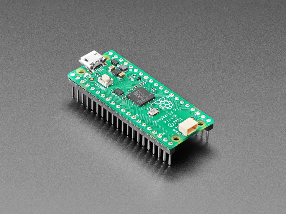
Raspberry Pi Pico H - Pico with Headers Soldered
Details
- Location: Cabinet-1, Bin 32
- Category: Microcontroller Boards
- Type: RP2040 Development Board with Pre-Soldered Headers (Pico Form Factor)
- Microcontroller: RP2040 (Dual ARM Cortex-M0+ @ 133MHz)
- Brand: Raspberry Pi Foundation
- Part Number: 5525
- Quantity: 1
- Product URL: https://www.adafruit.com/product/5525
Description
The Raspberry Pi Pico H is identical to the classic Pico but comes with pre-soldered headers and a new 3-pin debug connector. This makes it perfect for breadboard prototyping and development without requiring any soldering. The RP2040 microcontroller provides powerful dual-core performance at an affordable price.
Specifications
- Microcontroller: RP2040 dual-core ARM Cortex-M0+ @ 133MHz
- Memory: 264KB on-chip SRAM, 2MB on-board QSPI Flash
- GPIO Pins: 26 total (25 user-accessible + 1 LED)
- ADC: 3x 12-bit analog inputs (4th ADC used internally)
- PWM: 16 PWM channels
- Peripherals: 2x UART, 2x SPI, 2x I2C, USB 1.1 controller
- PIO: 2 blocks with 4 state machines each (8 total)
- Power: 1.8-5.5V input via USB or VSYS pin
- Logic Level: 3.3V (not 5V tolerant)
Dimensions
- Board Size: 21mm x 51mm (0.83” x 2.0”)
- Weight: ~3g
- Form Factor: Standard Pico compatible
Image
Features
- Pre-Soldered Headers: Ready for breadboard use without soldering
- 3-Pin Debug Connector: JST-SH connector for advanced debugging
- Dual-Core Performance: Two ARM Cortex-M0+ cores for multitasking
- PIO State Machines: Create custom hardware peripherals in software
- UF2 Bootloader: Drag-and-drop programming via USB mass storage
- Single Green LED: Connected to GPIO 25 for status indication
- BOOTSEL Button: Enter bootloader mode for firmware updates
- Breadboard Friendly: Standard 0.1” (2.54mm) pin spacing
- Low Power: Various power-saving modes available
Programming Support
- CircuitPython: Full support with extensive library ecosystem
- MicroPython: Official Raspberry Pi Foundation support
- Arduino IDE: Philhower Arduino core recommended
- C/C++ SDK: Official Raspberry Pi Pico SDK
- UF2 Bootloader: Simple drag-and-drop firmware installation
PIO (Programmable I/O) Capabilities
- Custom hardware peripherals created in software
- Perfect timing for protocols like NeoPixels, I2S, VGA
- 8 state machines total (2 blocks × 4 machines each)
- Can handle complex serial protocols without CPU intervention
- Runtime programmable in MicroPython and CircuitPython
Power Options
- USB Power: 5V via micro-USB connector
- External Power: 1.8-5.5V via VSYS pin
- 3.3V Output: 3.3V regulator provides up to 300mA
- Low Power Modes: SLEEP and DORMANT modes for battery operation
Debug Features
- 3-Pin Debug Connector: JST-SH connector for SWD debugging
- SWD Pins: SWCLK and SWDIO accessible via debug connector
- Reset Pin: Hardware reset capability
- Serial Debug: UART output for debugging
Tags
microcontroller, rp2040, pico, raspberry-pi, headers-soldered, debug-connector, circuitpython, micropython, arduino, pio, dual-core
Pinout Diagram
                    Raspberry Pi Pico H Pinout

                    +-----+
         +----------| USB |----------+
         |          +-----+          |
         | [ ]GP0/TX0              VBUS[ ] |
         | [ ]GP1/RX0              VSYS[ ] |
         | [ ]GND                   GND[ ] |
         | [ ]GP2                3V3_EN[ ] |
         | [ ]GP3                   3V3[ ] |
         | [ ]GP4               ADC_REF[ ] |
         | [ ]GP5                  GP28[ ] |
         | [ ]GND                  GND[ ] |
         | [ ]GP6                  GP27[ ] |
         | [ ]GP7                  GP26[ ] |
         | [ ]GP8                  RUN[ ] |
         | [ ]GP9                  GP22[ ] |
         | [ ]GND                  GND[ ] |
         | [ ]GP10                 GP21[ ] |
         | [ ]GP11                 GP20[ ] |
         | [ ]GP12                 GP19[ ] |
         | [ ]GP13                 GP18[ ] |
         | [ ]GND                  GND[ ] |
         | [ ]GP14                 GP17[ ] |
         | [ ]GP15                 GP16[ ] |
         |                               |
         |    [DEBUG]  [BOOTSEL]  [LED]  |
         +-------------------------------+

Debug Connector (3-pin JST-SH):
SWCLK | SWDIO | GND
Basic Wiring Examples
LED Blink Circuit
Pico GP25 → Built-in LED (no external wiring needed)
OR
Pico GP15 → LED Anode (long leg)
LED Cathode (short leg) → 220Ω Resistor → Pico GND
Button Input Circuit
Pico 3V3 → 10kΩ Pull-up Resistor → Pico GP2
Pico GP2 → Button → Pico GND

Code: digitalRead(2) returns HIGH when not pressed, LOW when pressed
I2C Device Connection (Default I2C0)
Pico 3V3 → Device VCC
Pico GND → Device GND
Pico GP4 (SDA) → Device SDA
Pico GP5 (SCL) → Device SCL
Add 4.7kΩ pull-up resistors on SDA and SCL lines
SPI Device Connection (Default SPI0)
Pico 3V3 → Device VCC
Pico GND → Device GND
Pico GP18 (SCK) → Device SCK
Pico GP16 (MISO) → Device MISO
Pico GP19 (MOSI) → Device MOSI
Pico GP17 (CS) → Device CS/SS
Analog Reading
Sensor Output → Pico GP26 (ADC0), GP27 (ADC1), or GP28 (ADC2)
Code: analogRead(A0) returns 0-65535 (0-3.3V)
Programming Setup Guide
CircuitPython Setup
- Download CircuitPython UF2 from circuitpython.org
- Hold BOOTSEL button while connecting USB
- Drag UF2 file to RPI-RP2 drive
- Board reboots as CIRCUITPY drive
- Edit code.py to program
Arduino IDE Setup
- Install Arduino IDE 2.0+
- Add RP2040 board package URL in preferences
- Install “Raspberry Pi Pico/RP2040” boards
- Select “Raspberry Pi Pico” from Tools → Board
- Hold BOOTSEL while connecting for first upload
MicroPython Setup
- Download MicroPython UF2 from micropython.org
- Hold BOOTSEL button while connecting USB
- Drag UF2 file to RPI-RP2 drive
- Use Thonny IDE or terminal for programming
Programming Examples
CircuitPython LED Blink
import board
import digitalio
import time

led = digitalio.DigitalInOut(board.LED)
led.direction = digitalio.Direction.OUTPUT

while True:
    led.value = True
    time.sleep(1)
    led.value = False
    time.sleep(1)
Arduino LED Blink
void setup() {
  pinMode(LED_BUILTIN, OUTPUT);  // GP25
}

void loop() {
  digitalWrite(LED_BUILTIN, HIGH);
  delay(1000);
  digitalWrite(LED_BUILTIN, LOW);
  delay(1000);
}
Notes
The Pico H is perfect for breadboard prototyping since the headers are already soldered. The 3-pin debug connector provides professional debugging capabilities. The RP2040’s PIO system is unique and powerful for creating custom peripherals. Important: Not 5V tolerant - all GPIO pins are 3.3V logic only. The UF2 bootloader makes programming incredibly simple - just hold BOOTSEL while plugging in USB to enter bootloader mode.