Important NoteThis entire repo was AI created - including all of the data within. The intent was to A) help me with my personal electronics inventory; and B) see how I could use AI to make that process a bit easier. DO NOT TRUST!
Seeed Studio XIAO RP2040
Details
- Location: Cabinet-1, Bin 32
- Category: Microcontroller Boards
- Type: RP2040 Development Board (XIAO Form Factor)
- Microcontroller: RP2040 (Dual ARM Cortex-M0+ @ 133MHz)
- Brand: Seeed Studio
- Part Number: 102010428
- Quantity: 1
- Product URL: https://wiki.seeedstudio.com/XIAO-RP2040/
Description
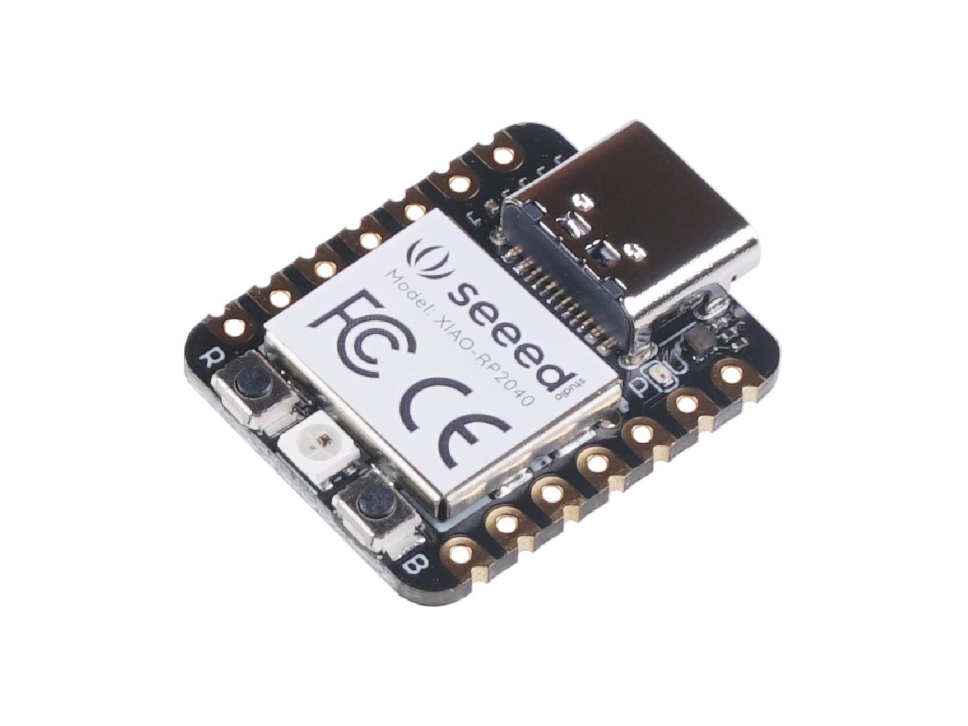
The Seeed Studio XIAO RP2040 is as small as the Seeed Studio XIAO SAMD21 but more powerful. It carries the powerful dual-core RP2040 processor with flexible clock running up to 133 MHz. Despite its tiny thumb-sized form factor (21x17.8mm), it packs 264KB of SRAM and 2MB of on-board Flash memory, making it perfect for wearable devices and small projects.
Specifications
- Microcontroller: Dual-core ARM Cortex M0+ processor up to 133MHz
- Logic/Power: 3.3V (5V tolerant via VIN pin)
- Memory: 264KB SRAM, 2MB Flash memory
- GPIO Pins: 14 total (11 digital, 4 analog)
- ADC: 4x 12-bit ADC channels
- Peripherals: 1x I2C, 1x SPI, 1x UART, 1x SWD
- PWM: 11 PWM pins
- USB: USB Type C connector with native USB support
- Special Features: Built-in RGB LED, Boot/Reset buttons
Dimensions
- Board Size: 21mm x 17.8mm x 3.5mm (0.8” x 0.7” x 0.1”)
- Weight: ~3g
- Form Factor: XIAO family compatible
Image
Features
- Powerful dual-core RP2040 processor up to 133MHz
- Rich on-chip resources with 264KB SRAM and 2MB Flash
- Flexible compatibility: Arduino, CircuitPython, MicroPython
- Breadboard-friendly & SMD design with no back components
- Thumb-sized form factor perfect for wearables
- Multiple interfaces: 11 digital pins, 4 analog pins, 11 PWM pins
- Compatible with XIAO expansion boards
- Built-in programmable RGB LED (reversed logic)
- UF2 bootloader support for easy programming
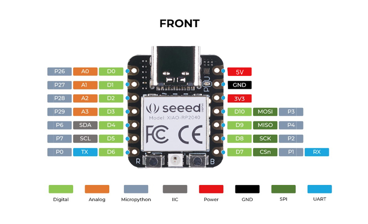
Pinout Diagram
Basic Wiring Examples
LED Blink Circuit
XIAO Pin D0 → LED Anode (long leg)
LED Cathode (short leg) → 220Ω Resistor → XIAO GND

Note: Built-in RGB LED available (reversed logic - LOW = ON)
Button Input Circuit
XIAO 3V3 → 10kΩ Pull-up Resistor → XIAO Pin D1
XIAO Pin D1 → Button → XIAO GND

Code: digitalRead(D1) returns HIGH when not pressed, LOW when pressed
I2C Device Connection
I2C Device VCC → XIAO 3V3
I2C Device GND → XIAO GND
I2C Device SDA → XIAO Pin D4 (SDA)
I2C Device SCL → XIAO Pin D5 (SCL)

Note: Built-in pull-up resistors included
SPI Device Connection
SPI Device VCC → XIAO 3V3
SPI Device GND → XIAO GND
SPI Device SCK → XIAO Pin D8 (SCK)
SPI Device MOSI → XIAO Pin D10 (MOSI)
SPI Device MISO → XIAO Pin D9 (MISO)
SPI Device CS → XIAO Pin D7 (CS)
Analog Sensor Reading
Sensor Output → XIAO Pin A0, A1, A2, or A3
Sensor VCC → XIAO 3V3
Sensor GND → XIAO GND

Code: analogRead(A0) returns 0-65535 (0-3.3V)
UART Communication
Device TX → XIAO Pin D7 (RX)
Device RX → XIAO Pin D6 (TX)
Device VCC → XIAO 3V3
Device GND → XIAO GND

Code: Serial1.begin(9600) for UART communication
Programming Setup Guide
CircuitPython Setup (Recommended)
- Download CircuitPython UF2 from circuitpython.org
- Hold BOOT button while connecting USB-C
- Drag UF2 file to RPI-RP2 drive
- Board reboots as CIRCUITPY drive
- Edit code.py to program
Arduino IDE Setup
- Install Arduino IDE 2.0+
- Add RP2040 board package URL in preferences
- Install “Raspberry Pi Pico/RP2040” boards
- Select “Seeed XIAO RP2040” from Tools → Board
- Hold BOOT while connecting for first upload
MicroPython Setup
- Download MicroPython UF2 from micropython.org
- Hold BOOT button while connecting USB-C
- Drag UF2 file to RPI-RP2 drive
- Use Thonny IDE or terminal for programming
Programming Examples
CircuitPython RGB LED Example
import board
import digitalio
import time

# RGB LED pins (reversed logic - LOW = ON)
led_r = digitalio.DigitalInOut(board.LED_RED)
led_g = digitalio.DigitalInOut(board.LED_GREEN)
led_b = digitalio.DigitalInOut(board.LED_BLUE)

led_r.direction = digitalio.Direction.OUTPUT
led_g.direction = digitalio.Direction.OUTPUT
led_b.direction = digitalio.Direction.OUTPUT

while True:
    # Red
    led_r.value = False  # ON
    led_g.value = True   # OFF
    led_b.value = True   # OFF
    time.sleep(1)

    # Green
    led_r.value = True   # OFF
    led_g.value = False  # ON
    led_b.value = True   # OFF
    time.sleep(1)

    # Blue
    led_r.value = True   # OFF
    led_g.value = True   # OFF
    led_b.value = False  # ON
    time.sleep(1)
Arduino RGB LED Example
#define LED_RED 17
#define LED_GREEN 16
#define LED_BLUE 25

void setup() {
  pinMode(LED_RED, OUTPUT);
  pinMode(LED_GREEN, OUTPUT);
  pinMode(LED_BLUE, OUTPUT);

  // Turn off all LEDs (HIGH = OFF for XIAO)
  digitalWrite(LED_RED, HIGH);
  digitalWrite(LED_GREEN, HIGH);
  digitalWrite(LED_BLUE, HIGH);
}

void loop() {
  // Red
  digitalWrite(LED_RED, LOW);   // ON
  digitalWrite(LED_GREEN, HIGH); // OFF
  digitalWrite(LED_BLUE, HIGH);  // OFF
  delay(1000);

  // Green
  digitalWrite(LED_RED, HIGH);   // OFF
  digitalWrite(LED_GREEN, LOW);  // ON
  digitalWrite(LED_BLUE, HIGH);  // OFF
  delay(1000);

  // Blue
  digitalWrite(LED_RED, HIGH);   // OFF
  digitalWrite(LED_GREEN, HIGH); // OFF
  digitalWrite(LED_BLUE, LOW);   // ON
  delay(1000);
}
CircuitPython I2C Scanner
import board
import busio

i2c = busio.I2C(board.SCL, board.SDA)

while not i2c.try_lock():
    pass

print("I2C addresses found:", [hex(device_address)
      for device_address in i2c.scan()])

i2c.unlock()
Arduino Analog Reading
void setup() {
  Serial.begin(115200);
  while (!Serial);
  Serial.println("XIAO RP2040 Analog Reading");
}

void loop() {
  // Read all 4 analog pins
  for (int i = 0; i < 4; i++) {
    int analogValue = analogRead(A0 + i);
    float voltage = analogValue * (3.3 / 65535.0);

    Serial.print("A");
    Serial.print(i);
    Serial.print(": ");
    Serial.print(analogValue);
    Serial.print(" (");
    Serial.print(voltage, 2);
    Serial.print("V)  ");
  }
  Serial.println();
  delay(1000);
}
Important Notes
Power Considerations
- 3.3V Logic: All GPIO pins are 3.3V logic level
- USB-C Power: Can be powered via USB-C or 3V3/5V pins
- Current Limit: 600mA peak from onboard regulator
- Battery Power: Supports battery power (disconnect USB when using battery)
Pin Limitations and Features
- ADC Pins: A0, A1, A2, A3 can be used for analog input (12-bit)
- PWM: 11 pins support PWM output
- I2C: One I2C peripheral (pins D4/D5)
- SPI: One SPI peripheral (pins D8/D9/D10)
- UART: One UART peripheral (pins D6/D7)
Special Features
- RGB LED: Built-in programmable RGB LED (reversed logic)
- BOOT Button: Hold for bootloader mode
- Reset Button: Single press to reset
- Compact Size: 21mm x 17.8mm - perfect for wearables
- XIAO Compatible: Works with XIAO expansion boards
Bootloader Mode
To enter bootloader mode:
- Hold BOOT button
- Connect USB-C cable
- Release BOOT button
- Board appears as RPI-RP2 drive
Reset
To reset the board:
- Press RESET button once while connected
- Board will restart current program
Tags
microcontroller, rp2040, xiao, seeed, usb-c, circuitpython, micropython, arduino, compact, breadboard-friendly
Notes
Perfect for wearable devices and small projects requiring powerful processing in a tiny form factor. Compatible with the entire XIAO ecosystem of expansion boards. The built-in RGB LED uses reversed logic (pull low to enable). Supports multiple programming environments including Arduino IDE, CircuitPython, and MicroPython. Easy bootloader mode access by holding B button while connecting USB.