Important NoteThis entire repo was AI created - including all of the data within. The intent was to A) help me with my personal electronics inventory; and B) see how I could use AI to make that process a bit easier. DO NOT TRUST!
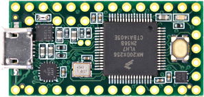
Teensy 3.2 Development Board
Details
- Location: Cabinet-1, Bin 28
- Category: Microcontroller Boards
- Type: ARM Cortex-M4 Development Board
- Microcontroller: MK20DX256VLH7
- Brand: PJRC
- Part Number: TEENSY32
- Quantity: 1
- Product URL: https://www.pjrc.com/store/teensy32.html
Description
Compact and powerful 32-bit ARM Cortex-M4 microcontroller development board featuring the MK20DX256VLH7 processor. Known for excellent audio processing capabilities, extensive I/O options, and robust software ecosystem. Popular choice for audio projects, LED control, and embedded applications requiring high performance in a small form factor.
Specifications
- Part Number: TEENSY32
- Microcontroller: MK20DX256VLH7 (Freescale Kinetis)
- Architecture: 32-bit ARM Cortex-M4 with DSP instructions
- Clock Speed: 72MHz (adjustable)
- Operating Voltage: 3.3V
- Input Voltage: 5V (via USB) or 3.3V-5.5V (via VIN)
- Flash Memory: 256KB
- RAM: 64KB
- EEPROM: 2KB (emulated)
- Dimensions: 35.6mm x 17.8mm x 3.2mm
- Weight: ~7g
Image
Features
- ARM Cortex-M4: High-performance 32-bit processor with DSP extensions
- USB Native: Built-in USB device support (12 Mbit/sec)
- Rich I/O: 34 digital I/O pins, 21 analog inputs, 1 analog output
- Audio Capabilities: I2S digital audio, built-in DAC, optimized audio library
- Communication: 3x UART, 2x I2C, 1x SPI, 1x CAN bus
- PWM: 12 pins with PWM capability
- Timers: Multiple hardware timers and interval timers
- Real-Time Clock: Built-in RTC with optional battery backup
- DMA: 16-channel DMA controller for high-performance transfers
Pin Configuration
- Digital I/O: 34 pins total (24 easily accessible on breadboard)
- Analog Inputs: 21 pins (A0-A20, 10-16 bit resolution)
- Analog Output: 1 pin (A14, 12-bit DAC)
- PWM: 12 pins (3, 4, 5, 6, 9, 10, 20, 21, 22, 23, 25, 32)
- Touch Sensing: 12 pins with capacitive touch capability
- Communication Pins:
- UART: Serial1 (pins 0,1), Serial2 (pins 9,10), Serial3 (pins 7,8)
- I2C: Wire (pins 18,19), Wire1 (pins 29,30)
- SPI: (pins 11,12,13,14)
- CAN: (pins 3,4)
- I2S: (pins 9,11,13,22,23)
Programming & Software
- Arduino IDE: Full support with Teensyduino add-on
- USB Types: Serial, MIDI, Keyboard, Mouse, Joystick, Audio, Raw HID
- Libraries: Extensive optimized library collection
- Audio Library: Visual design tool for audio processing
- Bootloader: Separate chip prevents corruption
- Programming: USB-based, no external programmer needed
Audio Capabilities
- I2S Digital Audio: Simultaneous input/output, up to 4 channels
- Built-in DAC: 12-bit analog output on pin A14
- Audio Library: Real-time audio processing with visual design tool
- S/PDIF: Digital audio output capability
- Audio Shield: Compatible with Teensy Audio Shield
Power & Timing
- Power Consumption: Low power modes available
- USB Power: 5V via USB, regulated to 3.3V
- External Power: 3.3V-5.5V via VIN pin
- Crystal: 16MHz with PLL for system clock
- RTC: 32.768kHz crystal support for real-time clock
Applications
- Audio Processing: Digital effects, synthesizers, audio analysis
- LED Control: NeoPixel/WS2812B strips, LED matrices
- MIDI Controllers: USB MIDI devices, musical instruments
- Data Logging: High-speed data acquisition
- Motor Control: PWM motor control, servo control
- Communication: CAN bus, multiple serial protocols
- Embedded Systems: Real-time control applications
Advantages
- High Performance: 72MHz ARM Cortex-M4 with DSP instructions
- Audio Optimized: Excellent for audio applications
- Rich Connectivity: Multiple communication protocols
- Mature Ecosystem: Extensive libraries and community support
- Small Form Factor: Compact design for space-constrained projects
- USB Flexibility: Multiple USB device types supported
Pinout Diagrams
Official PJRC Pinout Cards


Basic Wiring Examples
LED Blink Circuit
Teensy Pin 13 → Built-in LED (no external wiring needed)
OR
Teensy Pin 2 → LED Anode (long leg)
LED Cathode (short leg) → 220Ω Resistor → Teensy GND

Note: Pin 13 has built-in orange LED
Button Input Circuit
Teensy 3.3V → 10kΩ Pull-up Resistor → Teensy Pin 0
Teensy Pin 0 → Button → Teensy GND

Code: digitalRead(0) returns HIGH when not pressed, LOW when pressed
I2C Device Connection
I2C Device VCC → Teensy 3.3V
I2C Device GND → Teensy GND
I2C Device SDA → Teensy Pin 18 (SDA)
I2C Device SCL → Teensy Pin 19 (SCL)

Note: Built-in pull-up resistors included
Alternative I2C: Pin 29 (SCL1), Pin 30 (SDA1)
SPI Device Connection
SPI Device VCC → Teensy 3.3V
SPI Device GND → Teensy GND
SPI Device SCK → Teensy Pin 13 (SCK)
SPI Device MOSI → Teensy Pin 11 (MOSI)
SPI Device MISO → Teensy Pin 12 (MISO)
SPI Device CS → Teensy Pin 10 (CS)
Analog Sensor Reading
Sensor Output → Teensy Pin A0-A20 (21 analog inputs available)
Sensor VCC → Teensy 3.3V
Sensor GND → Teensy GND

Code: analogRead(A0) returns 0-1023 (default 10-bit)
Can be configured up to 16-bit resolution
Audio Output (DAC)
Audio Output → Teensy Pin A14 (DAC)
Connect to amplifier input or headphone circuit
Output range: 0-3.3V analog

Note: True 12-bit DAC, not PWM
Serial Communication
Device 1 (Serial1):
  Device TX → Teensy Pin 0 (RX1)
  Device RX → Teensy Pin 1 (TX1)

Device 2 (Serial2):
  Device TX → Teensy Pin 9 (RX2)
  Device RX → Teensy Pin 10 (TX2)

Device 3 (Serial3):
  Device TX → Teensy Pin 7 (RX3)
  Device RX → Teensy Pin 8 (TX3)

All serial ports independent, can run simultaneously
Programming Setup Guide
Arduino IDE + Teensyduino Setup
- Download and install Arduino IDE
- Download Teensyduino installer from PJRC.com
- Run Teensyduino installer (adds Teensy support to Arduino)
- Select “Teensy 3.2/3.1” from Tools → Board
- Connect Teensy via USB
- Upload code (automatic programming mode entry)
PlatformIO Setup
- Install PlatformIO IDE
- Create new project with “Teensy 3.2” board
- Use framework = “arduino” in platformio.ini
- Build and upload via PlatformIO
Programming Examples
Arduino Basic LED Blink
void setup() {
  pinMode(13, OUTPUT);  // Built-in LED
}

void loop() {
  digitalWrite(13, HIGH);
  delay(1000);
  digitalWrite(13, LOW);
  delay(1000);
}
Arduino Serial Communication
void setup() {
  Serial.begin(9600);   // USB Serial
  Serial1.begin(9600);  // Hardware Serial1
  Serial2.begin(9600);  // Hardware Serial2
  Serial3.begin(9600);  // Hardware Serial3
}

void loop() {
  // Echo data between USB and Serial1
  if (Serial.available()) {
    Serial1.write(Serial.read());
  }
  if (Serial1.available()) {
    Serial.write(Serial1.read());
  }
}
Arduino Analog Reading (High Resolution)
void setup() {
  Serial.begin(9600);
  analogReadResolution(16);  // Use 16-bit resolution
}

void loop() {
  int sensorValue = analogRead(A0);
  float voltage = sensorValue * (3.3 / 65535.0);  // Convert to voltage

  Serial.print("16-bit value: ");
  Serial.print(sensorValue);
  Serial.print(", Voltage: ");
  Serial.println(voltage, 4);

  delay(100);
}
Important Notes
Power Considerations
- 3.3V Logic: All GPIO pins are 3.3V logic level
- 5V Tolerant: Digital pins can accept 5V input signals
- USB Power: Powered via USB (5V) with onboard 3.3V regulator
- External Power: Can use 3.3V-5.5V on VIN pin
- Current Limit: 250mA maximum from 3.3V pin
Pin Capabilities
- Digital I/O: 34 pins total (24 breadboard-friendly)
- Analog Input: 21 pins (A0-A20) with up to 16-bit resolution
- Analog Output: 1 true DAC pin (A14) with 12-bit resolution
- PWM: 12 pins with hardware PWM
- Touch Sensing: 12 pins with capacitive touch capability
Special Features
- Audio Processing: Optimized for audio applications with Audio Library
- High-Speed USB: Native USB device support
- Multiple Serial: 3 independent hardware serial ports
- CAN Bus: Built-in CAN controller (requires external transceiver)
- Real-Time Clock: With optional crystal and battery backup
Programming Considerations
- Automatic Programming: Teensy Loader handles programming automatically
- Recovery Mode: Physical button for recovery from bad code
- Fast Compilation: Optimized toolchain for quick development
- Rich Libraries: Extensive library ecosystem from PJRC
Notes
- Discontinued product - no longer in production
- Recommended to migrate to Teensy 4.0/4.1 for new projects
- 5V tolerant inputs for easy interfacing
- Breadboard friendly with 0.1” pin spacing
- Optional headers included but not pre-soldered